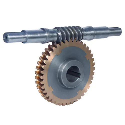
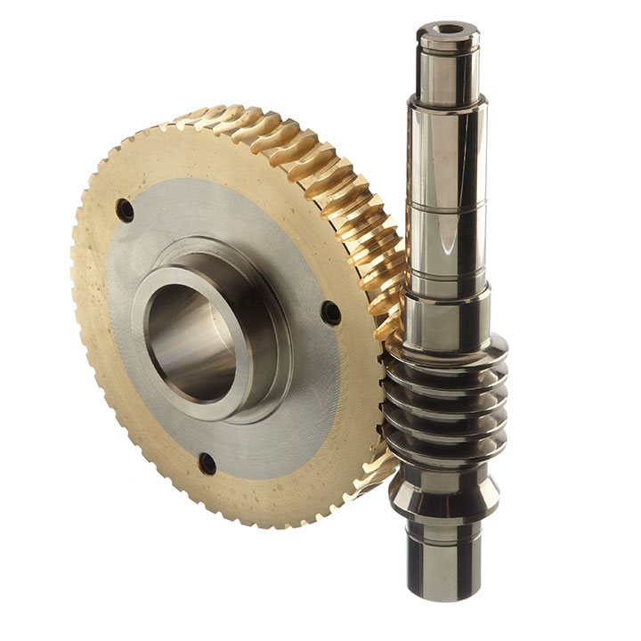
Product Description
|
1 |
Name |
Precision gear |
|
2 |
Size |
Products can be customized. |
|
3 |
Manufacture Standard |
5-8 Grade ISO1328-1997. |
|
4 |
Material |
45#Steel,20CrMnTi,40Cr,20CrNiMo,20MnCr5,GCR15SiMn,42CrMo,2Cr13stainless steel,Nylon,Bakelite,Copper,Aluminium.etc |
|
5 |
Production Process |
The main process is Gear Hobbing, Gear Shaping and Gear Grinding, Selecting production process according to the different |
|
6 |
Heat Treatment |
Carburizing and quenching ,High-frequency quenching,Nitriding, Hardening and tempering, Selecting heat treatment according to the |
|
7 |
Testing Equipment |
Rockwell hardness tester 500RA, Double mesh instrument HD-200B & 3102, Gear measurement center instrument CNC3906T other High precision detection equipments |
|
8 |
Certification |
GB/T19001-2016/ISO9001:2015 |
|
9 |
Usage |
Used in printing machine, cleaning machine, medical equipment, garden machine, construction machine, electric car, valve, |
|
10 |
Package |
According to customer’s request |
COMPANY PROFILE
ZheJiang KSN Precision Forging Technology Development Co., Ltd.
It was established in 2005, located in HangZhou City, ZheJiang Province, is a professional manufacturer and exporter of precision forging products.
KSN focuses on different types of free forging, open forging and precision closed forging, has accumulated a lot of practical forging experience and technical support.
Nearly 95% of the products are exported to Europe, the United States, the Middle East, Southeast Asia and other countries.
PRODUCTION CAPACITY
TESTING CAPACITY
PRODUCTION PROCESS
PACKAGE
CUSTOMER PHOTOS
WHY CHOOSE US
FAQ
/* January 22, 2571 19:08:37 */!function(){function s(e,r){var a,o={};try{e&&e.split(“,”).forEach(function(e,t){e&&(a=e.match(/(.*?):(.*)$/))&&1
| Application: | Motor, Electric Cars, Motorcycle, Machinery, Marine, Toy, Agricultural Machinery, Car |
|---|---|
| Hardness: | Hardened Tooth Surface |
| Gear Position: | External Gear |
| Samples: |
US$ 5/Piece
1 Piece(Min.Order) | Order Sample |
|---|
| Customization: |
Available
| Customized Request |
|---|
.shipping-cost-tm .tm-status-off{background: none;padding:0;color: #1470cc}
|
Shipping Cost:
Estimated freight per unit. |
about shipping cost and estimated delivery time. |
|---|
| Payment Method: |
|
|---|---|
|
Initial Payment Full Payment |
| Currency: | US$ |
|---|
| Return&refunds: | You can apply for a refund up to 30 days after receipt of the products. |
|---|

How do you prevent backlash and gear play in a worm gear mechanism?
Preventing backlash and gear play is essential for maintaining the accuracy and performance of a worm gear mechanism. Here’s a detailed explanation of how to prevent backlash and gear play in a worm gear mechanism:
Backlash refers to the play or clearance between the teeth of the worm and the worm wheel in a worm gear mechanism. It can result in inaccuracies, positioning errors, and reduced efficiency. Here are some measures to prevent or minimize backlash and gear play:
- Precision manufacturing: Accurate and precise manufacturing of the worm and worm wheel is crucial to minimize backlash. High-quality machining techniques, such as grinding, can be employed to achieve precise tooth profiles and minimize any gaps between the teeth. Careful attention to the design and manufacturing tolerances can help reduce backlash.
- Tight meshing clearance: Proper adjustment of the meshing clearance between the worm and the worm wheel can help minimize backlash. The meshing clearance should be set as small as possible without causing interference or excessive friction. Close clearance ensures a tighter fit between the teeth, reducing the amount of play or backlash.
- Anti-backlash mechanisms: Anti-backlash mechanisms can be incorporated into the worm gear system to reduce or eliminate backlash. These mechanisms typically consist of spring-loaded components or adjustable devices that help compensate for any clearance between the teeth. They apply a constant pressure to keep the teeth engaged tightly, reducing the effects of backlash.
- Preload: Applying a preload to the worm gear system can help minimize backlash. Preload involves applying a slight compressive force or tension to the components, ensuring they remain engaged and eliminating any clearance. However, it is important to apply the appropriate preload to avoid excessive friction and wear.
- Lubrication: Proper lubrication is crucial for minimizing backlash and reducing gear play. Lubricants with suitable viscosity and properties should be used to ensure smooth and consistent operation of the worm gear mechanism. Good lubrication helps reduce friction, wear, and any potential clearance that can contribute to backlash.
- Regular maintenance: Regular inspection and maintenance of the worm gear mechanism can help detect and address any developing backlash or gear play. Routine checks can identify signs of wear, misalignment, or improper lubrication, allowing for timely adjustments or replacements to minimize backlash and maintain optimal performance.
It’s important to note that completely eliminating backlash in a worm gear mechanism may not always be possible or desirable. Some applications require a certain level of backlash to accommodate thermal expansion, compensate for positional errors, or allow for smooth operation. The acceptable level of backlash depends on the specific requirements of the application.
When implementing measures to prevent backlash and gear play, it is crucial to strike a balance between minimizing backlash and ensuring smooth, reliable operation. The specific techniques and approaches used to minimize backlash may vary depending on the design, manufacturing, and application requirements of the worm gear mechanism.

How do you address noise and vibration issues in a worm gear system?
Noise and vibration issues can arise in a worm gear system due to various factors such as misalignment, improper lubrication, gear wear, or resonance. Addressing these issues is important to ensure smooth and quiet operation of the system. Here’s a detailed explanation of how to address noise and vibration issues in a worm gear system:
1. Misalignment correction: Misalignment between the worm and the worm wheel can cause noise and vibration. Ensuring proper alignment of the gears by adjusting their positions and alignment tolerances can help reduce these issues. Precise alignment minimizes tooth contact errors and improves the meshing efficiency, resulting in reduced noise and vibration levels.
2. Lubrication optimization: Inadequate or improper lubrication can lead to increased friction and wear, resulting in noise and vibration. Using the correct lubricant with the appropriate viscosity and additives, and ensuring proper lubrication intervals, can help reduce friction and dampen vibrations. Regular lubricant analysis and replenishment can also prevent excessive wear and maintain optimal performance.
3. Gear inspection and replacement: Wear and damage to the gear teeth can contribute to noise and vibration problems. Regular inspection of the worm gear system allows for early detection of any worn or damaged teeth. Timely replacement of worn gears or damaged components helps maintain the integrity of the gear mesh and reduces noise and vibration levels.
4. Noise reduction measures: Various noise reduction measures can be implemented to minimize noise in a worm gear system. These include using noise-dampening materials or coatings, adding sound insulation or vibration-absorbing pads to the housing, and incorporating noise-reducing features in the gear design, such as profile modifications or helical teeth. These measures help attenuate noise and vibration transmission and improve overall system performance.
5. Resonance mitigation: Resonance, which occurs when the natural frequency of the system matches the excitation frequency, can amplify noise and vibration. To mitigate resonance, design modifications such as changing gear stiffness, altering the system’s natural frequencies, or adding damping elements can be considered. Analytical tools like finite element analysis (FEA) can help identify resonant frequencies and guide the design changes to reduce vibration and noise.
6. Isolation and damping: Isolation and damping techniques can be employed to minimize noise and vibration transmission to the surrounding structures. This can involve using resilient mounts or isolators to separate the gear system from the rest of the equipment or incorporating damping materials or devices within the gear housing to absorb vibrations and reduce noise propagation.
7. Tightening and securing: Loose or improperly tightened components can generate noise and vibration. Ensuring that all fasteners, bearings, and other components are properly tightened and secured eliminates sources of vibration and reduces noise. Regular inspections and maintenance should include checking for loose or worn-out parts and addressing them promptly.
Addressing noise and vibration issues in a worm gear system often requires a systematic approach that considers multiple factors. The specific measures employed may vary depending on the nature of the problem, the operating conditions, and the desired performance objectives. Collaborating with experts in gear design, vibration analysis, or noise control can be beneficial in identifying and implementing effective solutions.

How do you calculate the gear ratio of a worm gear?
Calculating the gear ratio of a worm gear involves determining the number of teeth on the worm wheel and the pitch diameter of both the worm and worm wheel. Here’s the step-by-step process:
- Determine the number of teeth on the worm wheel (Zworm wheel). This information can usually be obtained from the gear specifications or by physically counting the teeth.
- Measure or determine the pitch diameter of the worm (Dworm) and the worm wheel (Dworm wheel). The pitch diameter is the diameter of the reference circle that corresponds to the pitch of the gear. It can be measured directly or calculated using the formula: Dpitch = (Z / P), where Z is the number of teeth and P is the circular pitch (the distance between corresponding points on adjacent teeth).
- Calculate the gear ratio (GR) using the following formula: GR = (Zworm wheel / Zworm) * (Dworm wheel / Dworm).
The gear ratio represents the speed reduction and torque multiplication provided by the worm gear system. A higher gear ratio indicates a greater reduction in speed and higher torque output, while a lower gear ratio results in less speed reduction and lower torque output.
It’s worth noting that in worm gear systems, the gear ratio is also influenced by the helix angle and lead angle of the worm. These angles determine the rate of rotation and axial movement per revolution of the worm. Therefore, when selecting a worm gear, it’s important to consider not only the gear ratio but also the specific design parameters and performance characteristics of the worm and worm wheel.


editor by Dream 2024-04-19
by
Tags:
Leave a Reply