Опис
NMRV-E130 — Extended Worm Shaft Design | 130mm Center Distance | Hollow Input with Flange
Engineered for rotary indexing tables and CNC feed drives, the NMRV-E130 from Ever-power Australia Worm Reducer Co., Ltd. delivers dependable speed reduction with die-cast aluminum alloy housing with ribbed fins. Trusted by OEMs and system integrators across 60+ countries.

📜 NMRV-E130 Product Overview
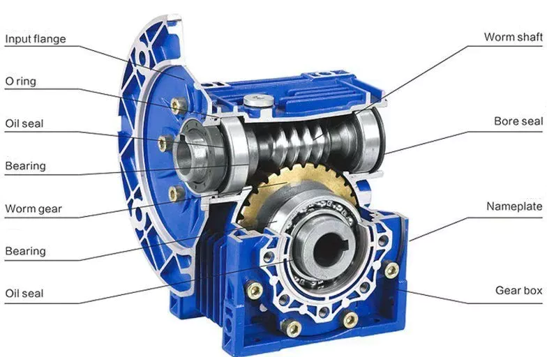
The NMRV-E130 is a precision-built worm gear speed reducer designed for reliable right-angle power transmission in demanding industrial environments. Featuring die-cast aluminum alloy housing with ribbed fins, this unit transforms high-speed motor rotation into controlled, high-torque output suitable for rotary indexing tables and CNC feed drives. The worm gear mechanism provides inherently smooth, low-vibration operation with significantly lower noise levels than spur or helical gear alternatives — typically below 65 dB(A) at rated load.
All gear components are manufactured under ISO 9001-certified quality management. The worm wheel is machined from wear-resistant bronze alloy, while the worm shaft undergoes carburizing and precision grinding to achieve a hardened tooth surface. This material combination ensures gradual, predictable wear characteristics rather than sudden failure, giving maintenance teams confidence in planning scheduled interventions.
✅ Key Features & Benefits
Ground worm shaft with Zi tooth profile ensures optimal contact geometry, reducing wear and maximizing transmission efficiency.
90° shaft arrangement saves space in tight machine envelopes compared to inline reducers of equivalent torque capacity.
A single gearbox covers a broad ratio spectrum, simplifying inventory management across multiple machine designs.
High-quality radial ball bearings support both shafts, providing excellent load capacity and minimizing axial play.
🔧 Technical Specifications
| Parameter | Value |
|---|---|
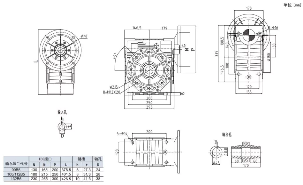
| Center Distance | 130 mm |
| Reduction Ratio | 5, 7.5, 10, 15, 20, 25, 30, 40, 50, 60, 80, 100 |
| Max Output Torque | 1050 Nm |
| Input Power Range | Up to 5.5 kW |
| Output Speed Range | 14–280 r/min |
| Housing | Die-cast Aluminum Alloy |
| Worm Wheel | CuSn12Ni2 Tin-Nickel Bronze |
| Worm Shaft | 20CrMnTi Steel, HRC 58-62, Zi Profile |
| Motor Flanges | 100/112B14, 132B5 |
| Protection | IP55 |
| Mounting | B3, B5, B6, B7, B8, V5, V6 |
| Weight | ~38 kg |
| Noise | < 65 dB(A) |
| Ambient Temp | -10°C to +40°C |
🏭 Application Industries
Mixers, dosing pumps, and rotary valves in hygienic production environments.
Thread winding, fabric tensioning, and screen-printing carriage drives.
Sliding gates, barrier arms, and rolling shutters for commercial access control.

📚 Selection & Sizing Guide
Proper sizing prevents premature failure. Follow this simplified procedure to confirm the NMRV-E130 suits your application:
Step 1: Calculate required output speed: n₂ = Motor Speed / Ratio
Step 2: Determine required output torque from your machine design.
Step 3: Apply service factor (fs) based on duty cycle, load type, and daily running hours.
Step 4: Verify M₂ × fs ≤ rated torque from the specification table above.
Step 5: Calculate motor power: P₁ = (M₂ × fs × n₂) / (9550 × η)
💡 Need help? Our engineering team provides free sizing assistance — contact us with your torque, speed, and application details.
🛠 Installation & Maintenance
☑ Mount on a flat, rigid surface with all foundation bolts properly torqued. ☑ Align motor and gearbox shafts within 0.5° angular and 0.05 mm parallel tolerance. ☑ Fill lubricant to the oil-gauge center line before first operation. ☑ Remove the breather vent plug to allow air circulation. ☑ Perform the first oil change after 100 operating hours, then every 2,500 hours thereafter. ☑ Maximum allowable oil temperature is 95°C — if exceeded, check load, alignment, and oil condition.

💧 Lubrication
Use synthetic PAG oil (ISO VG 460) for ambient temperatures 15–40°C, or ISO VG 320 for cooler environments. Recommended brands: Shell Tivela S, Mobil Glygoyle, or Esso Spartan EP series. Mineral oils are acceptable but result in higher operating temperatures and shorter change intervals. Fill to the sight-gauge center line.
🚧 Troubleshooting
| Symptom | Cause | Action |
|---|---|---|
| 🌡 Overheating | Overload / misalignment / low oil | Reduce load; re-align; check oil level |
| 📳 Vibration | Loose bolts / worn bearings | Re-torque fasteners; replace bearings |
| 🔈 Noise | Poor mesh / insufficient oil | Inspect gears; refill lubricant |
| 💧 Leakage | Worn seals / loose drain plug | Replace seals; tighten with sealant |
❓ Frequently Asked Questions
What materials are used in the gear set?
The worm wheel is precision-machined from CuSn12Ni2 tin-nickel bronze for exceptional wear resistance. The worm shaft is 20CrMnTi carburized alloy steel, ground to HRC 58-62 with Zi tooth profile for optimum meshing efficiency.
Can I mount this in any orientation?
Yes. Multiple mounting positions are supported including horizontal foot-mount, flange-mount, and vertical configurations. Ensure the oil level and breather are appropriate for your chosen orientation.
What is the typical service life?
Under rated conditions with proper lubrication and maintenance, service life regularly exceeds 20,000 operating hours. Bronze worm wheels exhibit gradual, predictable wear patterns rather than sudden failure.
How does efficiency vary with ratio?
Efficiency decreases as ratio increases. Low ratios (5-10:1) achieve 85-90%, medium ratios (20-30:1) achieve 68-82%, and high ratios (60-100:1) range from 44-60%. Select the lowest ratio that meets your speed requirement for best efficiency.
Can I combine two units for higher ratios?
Yes. Two units can be stacked in series for ratios up to 10,000:1. Alternatively, consider our double-reduction worm gearbox series which integrates both stages in a single housing.
⭐ Customer Feedback
⭐⭐⭐⭐⭐
“The dual IEC/NEMA compatibility saved us from redesigning our mounting plates. Brilliant engineering decision.”
— Sarah M., Design Engineer, UK 🇬🇧
⭐⭐⭐⭐⭐
“The machining quality rivals European brands at a fraction of the price. Our QC department was impressed.”
— Hans W., Engineering Lead, Germany 🇩🇪
Looking for a Reliable Worm Reducer Supplier?
Ever-power serves OEMs and distributors in 60+ countries. Volume pricing, custom branding, and dedicated engineering support available.
Ever-power Australia Worm Reducer Co., Ltd. • About Us


